The fundamental purpose of any lighting scheme is to provide adequate illumination for the area being lit. For some areas, lighting may need to be adjusted in brightness or switched on or off as required. A simple light switch is OK for many purposes but there are real benefits with more sophisticated control.
Dimming and Lighting Control
Dimming
Dimming is a function which allows lighting equipment to operate at a different brightness other than maximum. Usually, it is expressed as a percentage of the power or light output, between 0% and 100%.
In a traditional incandescent light bulb, the electricity causes a metal filament to glow very brightly, producing light. This is usually powered directly from the mains AC (alternating current) supply. If the amount of mains electrical power flowing through the bulb is reduced, it will glow less brightly.
Resistive Mains Dimmers
Dimming was originally achieved using a variable resistor, which reduces the flow of electricity as the resistance is increased.
The result is an overall reduction in the positive and negative sweep of the alternating current as shown in the diagram opposite.
The problem with this method is that the resistor dissipates a lot of electrical energy as heat, causing this method of dimming to be very inefficient.

TRIAC Mains Dimmers
A solution to this problem is to use a device called a TRIAC dimmer, which can control the AC power electronically. (TRIAC is short for TRIode for AC)
The TRIAC is a device that can “switch off” part of the current each time it alternates from positive to negative. This effect is called “phase cutting” and is described in the diagram opposite.
This type of dimmer is known as a “Leading Edge” dimmer, since it chops off the front or leading part of each positive or negative half-cycle of the alternating current.
The amount that is “chopped off” determines how much electrical energy overall that is delivered to the lamp(s).

With a traditional incandescent lamp (light bulb), TRIAC dimming works very well, since the filament will be heated less overall by the “chopped off” AC current. The chopping effect is not visible because this happens 50 or 60 times per second, which doesn’t give enough time between cycles for the filament to cool.
This is not the case, however, with LED lamps, which do not generate light as a result of heating a filament and as a result can switch on and off almost instantaneously. Furthermore, the mains AC supply must be converted into DC at a specific voltage to be suitable to power the LED lamp. This task is performed by the LED driver, which is often built into the lamp to enable it to connect directly to the mains supply as a replacement for traditional filament bulbs.
Unfortunately, a standard LED driver depends upon the smooth AC sine wave to be able to convert it into the appropriate DC voltage for the LED and when a TRIAC dimmer is used, the result is disastrous with severe and random flickering of the LED.
LED Dimming
The answer is to use a dimmable LED driver. If this is built into the LED lamp, it is called a dimmable LED lamp. This driver converts the TRIAC-chopped AC power supply into DC at a suitable voltage for the LED and then chops this up into very much faster bursts of DC power. This causes the LED to flicker much faster than the human eye can detect and gives the overall effect of dimming the LED source.
As the dimmer is set to higher settings, the time that the pulse is “on” for is increased. As the dimmer is set to lower settings, the time that the pulse is “off” for is increased.
This is known as Pulse Width Modulation (or PWM) dimming.
PWM dimming is more effective than controlling the current or voltage level, since the LED operates to an optimum current and voltage combination already, as detailed in our support article about LED Drivers.

Trailing Edge Mains Dimmers
For many dimmable LED drivers, a TRIAC Leading Edge dimmer is not compatible. For these drivers, a different device, called a Trailing Edge or Reverse Phase dimmer is required.
Like a TRIAC dimmer, the Trailing Edge dimmer also controls the supply of electrical energy to the lamp by chopping away part of the AC cycle but this time it is at the end or “trailing” edge of each cycle.
A more sophisticated IC (integrated circuit) design is needed to control the power in this way and this type of dimmer generally give a smoother, more stable power control

Lighting Control
All lighting requires some kind of control and there are different methods with different levels of sophistication.
The most basic method of control is a simple power on/off switch.
Controls which can also control the brightness of light output include the following…
• Manual Dimming – manual rotary or slider control for either resistive or TRIAC dimmers
• Switch Dimming – enables both on/off and brightness control from a simple momentary switch
• Control Voltage (CV) Dimming – control of dimmable driver or power supply from a 0 to 10V signal.
• DALI Control – Digital Addressable Lighting Interface designed for large commercial lighting schemes.
• Wireless Remote Control – Remote control via Radio frequency (RF), WiFi, Mesh or Bluetooth protocols.
In addition to the above controls, lighting may be automated using motion detectors.
Manual Control
Manual dimmers are usually a direct replacement for a wall light switch and are operated via a rotary or slider control to adjust the amount of power to the lamp(s) and as a result set the brightness of the light output.

Switch Dimming
In a similar way to rotary- or slider-controlled dimmers, Switch dimmers enable manual control over the power delivered to the lamp(s) but this time via a push switch or touch pad.
Some Switch Dimmers offer a range of pre-set brightness levels which are stepped through in sequence each time the light is switched on and off as shown below (example shows 100% - 50% - 25% - 100% cycles)

Other Switch Dimmers use a dimming curve that fades down and back up again as a momentary switch is held down. Releasing the switch sets the brightness to the current dimming level and brief presses of the switch will simply switch the light on or off, remembering the current brightness setting until it is re-set by holding down the switch. An example dimming profile is shown in the diagram below.

Control Voltage (CV) Dimming
A mains dimmer is limited by the capacity of its internal components, so there is a limit to how many lamps it can control. A solution to this would be to have many individual dimmers being controlled by a single control voltage.
Control Voltage (CV) dimming uses a wall-mounted or other control to send a low voltage DC signal to many separate dimmer modules or PWM LED drivers. The standard type is from 0 to 10 Volts (0-10V), where 0V is 0% and 10V is 100% light output.
For LED lighting, this method can only operate with CV dimmable LED drivers or luminaires. 0-10V control may also be used in conjunction with some other dimming protocols that are detailed below.

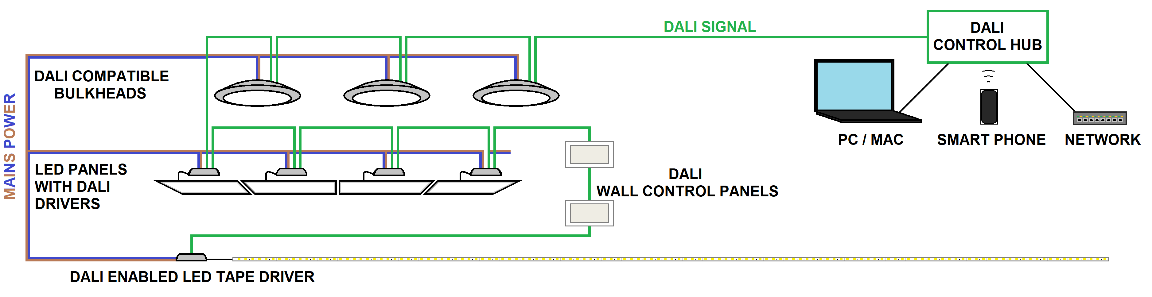
DALI Dimming
DALI is an abbreviation for Digital Addressable Lighting Interface and is used to control large and sophisticated lighting schemes in commercial buildings. This is a digital signal which can address each section of lighting or even individual luminaires and apply on/off or dimming control remotely. To use this system, each LED driver or lighting control gear needs to be compatible with DALI control. The DALI signal is carried along a pair of data cable wires and is daisy-chained from one luminaire or driver to another.
Wireless Control
Besides DALI and 0-10V dimming, lighting may be controlled wirelessly to avoid running additional signal cables. There are several different types of wireless signal that can be employed, and all of these have some limitations.
Standard Radio Frequency (RF) remote control uses a fixed frequency (433.92MHz in the UK), which is the same frequency used to operate garage doors, RC cars and many other domestic devices. This type of basic RF control uses a very fast sequence of ON and OFF pulses which are encoded to only address the required lighting section and set the on/off or dimming value.
Control is usually transmitted from a handset to each section of lighting or to multiple lighting fixtures from a control hub. The limitation is that the controller and lighting dimmers or switches must be specifically designed to work together and must be in wireless range of each other.
WiFi Control
WiFi offers a more convenient control platform for lighting since it is a digital signal and can operate through the existing wireless local area network (WLAN). It is also possible to purchase high power wireless access points and extenders to give full wireless coverage to the lighting scheme. The number of lighting fixtures being controlled is only limited by the number of IP addresses available on the network.
Wireless mesh technology can be used as part of a WiFi or other wireless control system and differs in the fact that each Node (luminaire or LED driver) can both receive and send the wireless signal.
This means that it can relay the wireless signal to other nodes within wireless range, acting as a wireless extender. Such systems usually detect nearby nodes and build a virtual network or mesh and can also intelligently detect any faults or control issues in the system.
The WiFi transceiver may even be built into the lamp, as is the case for “smart bulbs”, which can also provide RGB colour mixing.

Closed Wireless Control Systems
Specialized and proprietary wireless control systems are also available that operate within either the WiFi or completely different RF frequency band. These will mostly only operate with other products with the same format or brand as a closed system. Some examples of this are Casambi, Z-Wave and Zigbee.
Bluetooth Lighting Control
Bluetooth is another wireless technology that is widely used but was originally developed to stream data (such as audio) from one device to another at short range.
More recently, a new protocol has been developed called BLE, which stands for Bluetooth Low Energy. This type of Bluetooth uses a very minimal amount of electricity to transmit very simple instructions (rather than a data stream) from one device to another and the receiving device can then relay this to a further device.
This receive-and-transmit capability enables the system to create a network of nodes to expand the coverage range of the control signals to create a network called a “BLE Mesh”

Lighting Automation
Digital lighting control interfaces, such as DALI, WiFi, BLE Mesh or other proprietary formats can each be controlled from a central hub or integrated with other controllers to provide some automation for the lighting scheme.
This may be based on a timer schedule or even integrated with separate detectors, such as door switches and motion detectors, using an “if this then that” (IFTTT) to control the lighting in an area.
Some control hubs can also be connected to a smart phone for handheld remote control and programming of the lighting schedule.
Occupancy and Twilight Detectors
In addition to the intelligent control described above, there are also more straightforward types of lighting automation that may be less flexible but require minimal programming and can be provided at a much lower cost.
An occupancy detector is any device that aims to detect the presence of people within a given area and control the lighting as a result. The required function might be to switch lighting off or to a dimmer setting when there are no people occupying the area. When motion is detected, the lighting can be triggered to switch fully on automatically and stay lit for a pre-determined length of time before switching off again. There are 2 main different types of occupancy detectors, which are described below.
P.I.R. stands for Passive Infra-Red, which is a type of light detector which looks for changes in the infra-red region of light. Infra-red is emitted by heat from people’s bodies and the P.I.R. sensor can “see” any movements of warm objects within its field of view, which causes it to open an electronic switch (called a relay) which in turn switches power to the lighting. P.I.R. sensors are ideal to detect motion in a specific area.

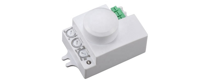
Microwave sensors do not rely on heat to detect occupancy but instead emit a low power microwave signal and listen for changes in the reflections received back. This uses the Doppler effect where if an object is moving, it will distort the frequency of the microwave signal as it is reflected back to the sensor.
The benefit of the microwave sensor is that it can be built inside a luminaire because it does not need to “see” like the P.I.R. detector does. The disadvantage of microwave sensors is that they travel through walls and floors, so can be triggered from beyond the space where they are located and are therefore, less discriminate.
Twilight Detectors
A twilight detector is a device that measures the level of ambient light and triggers a relay below a set threshold. The relay will, in turn, switch power to the lighting when the threshold is crossed, usually from daylight to darkness. The device that performs this function is called a Photocell, which responds to visible light. The twilight detector might also be incorporated within a P.I.R. detector to provide motion triggering only in the hours of darkness.
Lighting automation and dimming in general provide practical ways of reducing energy usage, which is a major benefit in a world where ecology and waste reduction are becoming ever more important.