

D1800
D-Series Class-D Power Amplifiers
172.118UK
Introduction
Thank you for choosing a Citronic D-series quad power amplifier as part of your sound reinforcement system.
These amplifiers use Class-D circuit architecture for lightweight and efficient performance. Please read this manual fully and follow the instructions to achieve the best results from your amplifier and to avoid damage through misuse.

Warning
To prevent the risk of fire or electric shock, do not expose any of the components to rain or moisture.
If liquids are spilled on the casing:
- Stop using immediately.
- Allow the unit to dry out.
- Have it checked by qualified personnel before further use.
Avoid impact, extreme pressure, or heavy vibration to the case.
No user-serviceable parts inside.
Do not open the case. Refer all servicing to qualified service personnel.
Safety
- Check for correct mains voltage and condition of IEC lead before connecting to power outlet.
- Ensure speaker leads are in good condition with no shorted connections or damaged plugs.
- Check that the impedance of speaker loads does not exceed the minimum stated load for the amplifier.
- Do not allow any foreign objects to enter the case or through the ventilation grilles.
Placement
- Keep out of direct sunlight and away from heat sources.
- Keep away from damp or dusty environments.
- When rack-mounting, ensure adequate support for the base of the amplifier and firm fixings for the front.
- Ensure adequate airflow and do not cover cooling vents at the front and rear of the amplifier.
- Ensure adequate access to controls and connections.
Cleaning
- Disconnect from the mains power supply before cleaning.
- Use a soft cloth with a neutral detergent to clean the casing as required.
- Use a vacuum cleaner to clear ventilation grilles of any dust or debris build-ups.
- Do not use strong solvents for cleaning the unit.
Front panel

- Ventilation grille: Do not Cover
- Channel A status LEDs
- Channel A output level control
- Power status LEDs
- Channel B output level control
- Channel B status LEDs
- Power on/off switch
Rear panel
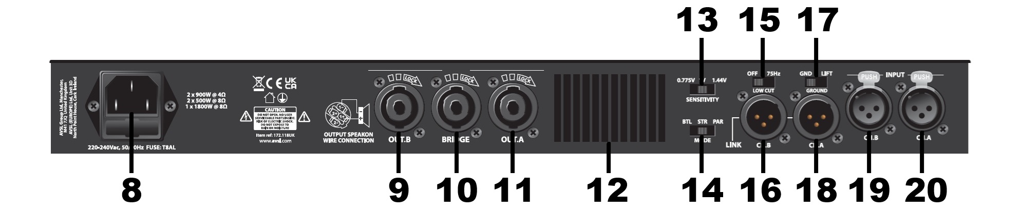
- IEC power inlet and fuse holder
- Channel B speaker output (SPK)
- Bridge mode speaker output (SPK)
- Channel B speaker output (SPK)
- Ground Lift switch
- SENSITIVITY selector
- MODE selector
- LOW CUT filter switch
- Channel B signal link output (balanced XLR)
- Ground Lift switch
- Channel A signal link output (balanced XLR)
- Channel B signal input (balanced XLR)
- Channel A signal input (balanced XLR)
Power requirements
- Power supply: mains 220-240Vac, 50/60Hz (IEC)
- Use the provided IEC power lead or an approved equivalent.
Installation
- Unpack the unit and verify that the D-series amplifier is intact and supplied with the IEC power lead(s)
- The unit can be used free-standing or for rack-mounting, remove the feet from the underside by unscrewing them.
- The unit may be rack-mounted into a single unit height of a 19" rack using the front mounting points.
- Ensure that no excessively heavy equipment is pressing down onto the D-series housing.
- Before connecting to mains power, make sure all output level controls are fully down and the power switch is off.
Setting Up
Connect speaker cabinets to outputs A and B using good quality Speakon® leads (9, 11).
Ensure the combined load on each channel is no lower than 4Ω.
Speaker Load Notes
Most PA speakers have a nominal impedance of 8Ω.
- One 8Ω speaker per output = OK
- Two 8Ω speakers wired in parallel (+ to + and − to −) = 4Ω load
- If a speaker has 2 inputs wired in parallel, connecting a speaker to one of these connections combined their loads in parallel.
- Never connect 2 separate amplifiers to parallel-wired connectors on a speaker cabinet.
Ensure that speakers can handle the power delivered at the rated (or combined) load impedance.
Amplifier Modes
Each pair of channels has a MODE switch (9, 14). Speakon plug wiring in all cases is on Pin 1+ and Pin 1-
Stereo Mode (default)
Each input feeds its corresponding output: - A → A - B → B
Parallel Mode
Inputs are summed to mono. A+B receive a mono mix of both inputs A and B.
Bridge Mode (BTL)
Bridge Tied Load combines two amplifier channels into one higher-power output.
Input is on channel A, output is mono from the BRIDGE socket
WARNING: Minimum load in Bridge Mode is 8Ω.
SENSITIVITY selector
Select between 0.775V, 1V, 1.44V, depending on the input signal strength. Standard line level is 0.775V (this is the RMS voltage at 0dB)
LOW CUT
The D-series amplifiers have a LOW CUT switch to remove frequencies below 75Hz, which the speakers may not be suitable for. The energy generated for these low frequencies is often wasted as heat in the speaker or can even cause damage to the voice coil. Leave this switched off for use with sub-woofers or full-range speakers capable of reproducing these low frequencies.
Input Connections
Connect mixer or line-level outputs to rear-panel XLR inputs (19,20). If the input signal is to be cascaded onto further amplifiers, connect these from the signal link outputs (16,18)

Balanced Wiring
| Function | Pin |
|---|---|
| Signal Hot (+) | 2 |
| Signal Cold (-) | 3 |
| Ground | 1 |
Unbalanced Wiring
| Function | Pin |
|---|---|
| Signal Hot (+) | 2 |
| Ground | 1 + 3 |
Powering Up
- Connect mains supply to IEC inlet (8).
- Ensure IEC lead is earthed and secure.
- Turn all channel controls fully down.
- Press power switch (7).
The amplifier uses a soft-start circuit and may take a few seconds before becoming operational.
Setting Levels
- Keep mixer output low.
- Increase amplifier channel levels to desired setting (typically full).
- Gradually raise mixer output until sound is heard.
- Continue increasing to the required operating level.
If excessive 50Hz hum is present:
- Switch GROUND LIFT (17) from GND to LIFT.
LED Indicators
Channel LEDs
Each channel includes:
- POWER (shows that power is on to the amplifier)
- SIGNAL (shows that a signal is present)
- CLIP
- PROTECT
CLIP LED
The CLIP LED indicates amplifier overload. Brief flashes on peaks or transients (e.g.bass drum beat) are normal. If CLIP remains on continuously: - Reduce source level. - Reduce channel gain.
PROTECT LED
If this LED stays lit, the amplifier has self-protected. Switch off the power and remove connections, then power up again. If the fault is not cleared, refer the amplifier to qualilfied service engineer. If the fault is cleared, check all connections and speaker loads and reconnect , then try the amplifier again.
Powering Down
Turn down the output level controls before powering down the D-series amp to avoid loud noises through any connected equipment.
Troubleshooting
| Problem | Solution |
|---|---|
| POWER LED not lit | Check IEC connection and mains outlet |
| POWER LED on but no output | Check signal source and gain controls |
| SIGNAL LEDs active but no output | Check speakers and speaker leads |
| PROTECT LED is lit | Disconnect mains, check leads and speakers, restart |
| Still in Protect Mode | Refer to qualified service personnel |
| Distorted output and LIMIT LEDs active | Check sensitivity setting, reduce input signal level |
| Very low output | Verify line-level source and select lower sensitivity voltage |
Disposal and recycling
Dispose of this product in accordance with local environmental regulations. Do not dispose of electronic equipment with household waste.
Compliance
This product complies with applicable LVD safety and EMC standards.
Specification
| Specification | Value |
|---|---|
| Weight | 4.60kg |
| Bridge power @ 8 Ohms | 1 x 1800W |
| Power rms @ 8 Ohms | 2 x 500W |
| Power rms @ 4 Ohms | 2 x 900W |
| Fuse | T8A (20 x 5mm) |
| Dimensions | 482 x 350 x 44mm |
| Power supply | 220-240Vac, 50/60Hz (IEC) |
| Modes | Stereo, Parallel (mono), Bridge (mono) |
| Input sensitivity | 0.775V - 1.0V - 1.44V switchable |
| Low-cut filter | 75Hz switchable |
| Input connections | L+R XLR female (L+R XLR male through) |
| Output connections | L+R SPK connectors (+1 for bridge mode) |
Precautions
 |
CAUTION |  |
| RISK OF ELECTRIC SHOCK DO NOT OPEN | ||
| CAUTION : TO REDUCE THE RISK OF ELECTRIC SHOCK, DO NOT REMOVE COVER (OR BACK) NO USER-SERVICEABLE PARTS INSIDE REFER SERVICING TO QUALIFIED SERVICE PERSONNEL | ||
This symbol indicates that dangerous voltage constituting a risk of electric shock is present within this unit
This symbol indicates that there are important operating and maintenance instructions in the literature accompanying this unit
Safety Notice
- Prior to use, read through this safety guide.
- Pay attention to safety warnings.
- Observe all operating requirements.
- For any items designed for indoor use only, do not operate near water or in humid environments.
- For cleaning, only use a lint-free, dry cloth.
- Install according to the specifications.
- Place away from heat sources or heating appliances.
- During placement, ensure adequate support for the product and access to controls and connectors.
- Do not obstruct any cooling vents or openings and allow adequate space for air flow.
- Use only power connections supplied with the product or suitable equivalents.
- Do not modify the equipment in any way.
- For any mains powered appliances, ensure that the mains voltage is as described in the specifications.
- Keep powered products and batteries away from the reach of children.
- In case of malfunction, water ingress or other damage, consult qualified service personnel.
- Avoid pressure or impact to the housing that may result in damage when transporting or installing this product.
- For any Earthed mains product, ensure that the power supply has a protective Earth connection.
- Keep all packaging materials out of reach of children.

Indoor use only : The "House" symbol identifes electrical equipment designed primarily for indoor use.

Disposal : The "Crossed Wheelie Bin" symbol on the product means that the product is classed as Electrical or Electronic equipment and should not be disposed with other household or commercial waste at the end of its useful life. The goods must be disposed of according to your local council guidelines.

AVSL Group Ltd, Unit 2 Bridgewater Park, Taylor Road, Manchester, M41 7JQ, Unitied Kingdom

AVSL (EUROPE) Ltd, Unit 3D North Point House, North Point Business Park, New Mallow Road, Cork, Ireland


